| السلسلة | WRB_S-3WR2 |
|---|
| الطراز | WRB1215S-3WR2 |
|---|
| النوع | محولات DC/DC |
|---|
| العلامة التجارية | MORNSUN |
|---|
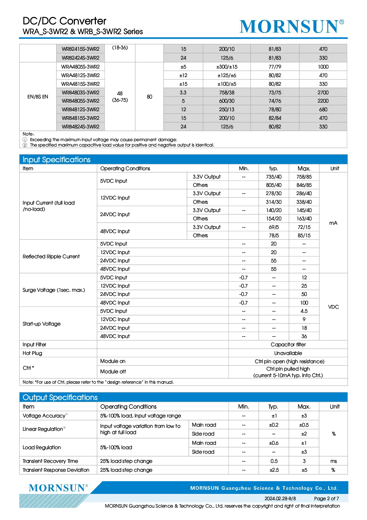
| Input Current (full load | 3.3V Output: 735/40 typ, 758/85 max; Others: 805/40 typ, 846/85 max; 3.3V Output: 278/30 typ, 286/40 max; Others: 314/30 typ, 338/40 max (5VDC Input; 12VDC Input) |
|---|
| /no-load) | 3.3V Output: 140/20 typ, 145/40 max mA; 24VDC Input: mA; Others: 154/20 typ, 163/40 max mA; 3.3V Output: 69/5 typ, 72/15 max mA; 48VDC Input: mA; Others: 78/5 typ, 85/15 max mA; 5VDC Input: 20mA; 12VDC Input: 20mA |
|---|
| تيار التموج المنعكس | 24VDC Input: 55; 48VDC Input: 55; 5VDC Input: -0.7–12; 12VDC Input: -0.7–25 |
|---|
| جهد الاندفاع (بحد أقصى 1 ثانية) | 24VDC Input: -0.7–50 VDC; 48VDC Input: -0.7–100 VDC; 5VDC Input: 4.5 VDC; 12VDC Input: 9 VDC |
|---|
| Start-up Voltage | 24VDC Input: 18; 48VDC Input: 36 |
|---|
| مرشح الدخل | Capacitor filter |
|---|
| التوصيل أثناء التشغيل | Unavailable; Module on: Ctrl pin open (high resistance) |
|---|
| Ctrl | Ctrl pin pulled high; (current 5-10mA typ. into Ctrl.) (Module off) |
|---|
| Voltage Accuracy ① | 5%-100% load, input voltage range: ±1 typ, ±3 max; Input voltage variation from low to Main road: ±0.2 typ, ±0.5 max |
|---|
| Linear Regulation ② | high at full load Side road: ±2%; Main road: ±0.6% typ, ±1% max |
|---|
| تنظيم الحمل | ±3% (Side road) (5%-100% load) |
|---|
| Transient Recovery Time | 0.5 ms typ, 3 ms max (25% load step change) |
|---|
| Transient Response Deviation | ±2.5% typ, ±5% max (25% load step change) |
|---|
| معامل درجة الحرارة | Full load: ±0.02 %/℃ typ, ±0.03 %/℃ max; WRB1212S-3WR2: %/℃; WRB1215S-3WR2: 70 %/℃ typ, 100 %/℃ max; WRB4824S-3WR2: %/℃; WRB1224S-3WR2: %/℃ |
|---|
| Ripple & Noise ③ | WRB2415S-3WR2: mVp-p; WRB2424S-3WR2: 100mVp-p typ, 150mVp-p max; WRA4805S-3WR2: mVp-p; WRB4803S-3WR2: mVp-p; Others: 40mVp-p typ, 75mVp-p max (20MHz bandwidth) |
|---|
| حماية من قصر الدائرة | Continuous, self-recovery |
|---|
| العزل (الدخل–الخرج) | VDC (Electric Strength Test for 1 minute with a) |
|---|
| العزل | 1500 VDC |
|---|
| مقاومة العزل | Input-output resistance at 500VDC: 1000 MΩ |
|---|
| سعة العزل | 120 pF (Input-output capacitance at 100kHz/0.1V) |
|---|
| درجة حرارة التشغيل | -40–+85℃ (See Fig. 1) |
|---|
| درجة حرارة التخزين | -55 to +125℃ |
|---|
| مادة الغلاف | Black plastic; flame-retardant and heat-resistant |
|---|
| الأبعاد | 22.00 × 9.50 × 12.00 mm |
|---|
| الوزن | 4.5g(Typ.) |
|---|
| طريقة التبريد | Free air convection |
|---|
| Electromagnetic | compatibility (EMC) |
|---|
| CE | CISPR32/EN55032 CLASS B (see Fig. 3-② for recommended circuit) |
|---|
| RE | CISPR32/EN55032 CLASS B (see Fig. 3-② for recommended circuit) |
|---|
| ESD | IEC/EN61000-4-2 Contact ±4kV perf. Criteria B |
|---|
| RS | IEC/EN61000-4-3 10V/m perf. Criteria A |
|---|
| EFT | IEC/EN61000-4-4 ±2kV (see Fig. 3-① for recommended circuit) perf. Criteria B |
|---|
| Surge | IEC/EN61000-4-5 line to line ±2kV (see Fig. 3-① for recommended circuit) perf. Criteria B |
|---|
| CS | IEC/EN61000-4-6 3 Vr.m.s perf. Criteria A |
|---|
| interruptions and | IEC/EN61000-4-29 0%, 70% perf. Criteria B |
|---|
| Typical Characteristic | Curves; Fig 1 |
|---|
| All DC-DC converters of this | series are tested before delivery using the recommended circuit shown in Fig. 2. |
|---|
| Input and/or output ripple can | be further reduced by appropriately increasing the input & output capacitor values C1, C2, C3 and C4 |
|---|
| and/or by selecting capacitors | with a low ESR (equivalent series resistance). C3 is used to reduce ripple. No need to add C3, if ripple |
|---|
| meets the demand. Appropriate | filter capacitance shall be chosen, start-up problems may be caused if the capacitance is too large. For |
|---|
| each output circuit, under the | condition of safe and reliable operation, the max. capacity of its filter capacitor should be lower than the |
|---|
| Single | Vin 5VDC&12VDC 24VDC&48VDC; C1 100µF/25V 10µF/100V; C2 47µF/25V 1µF/100V; Lin 4.7µH-12µH |
|---|
| Dual | C3 10µF/50V-22 µF/50V; C4/C5 100µF/50V(Typ.); Lout 2.2µH-10µH; Cd 47nF/100V; Fig. 2 |
|---|
| 2. EMC compliance | circuit; Fig. 3 |
|---|
| Model Vin: | 5VDC Vin: 12VDC Vin: 24VDC Vin: 48VDC |
|---|
| FUSE | Slow-blow, selecting based on needs |
|---|
| MOV | -- S14K20 S20K30 S14K60 |
|---|
| C0 | 680µF/25V 680µF/25V 330µF/50V 330µF/100V |
|---|
| C1 | 4.7µF/50V 4.7µF/100V |
|---|
| LDM1 | 12µH |
|---|
| C2 | 4.7µF/50V 4.7µF/100V |
|---|
| C3 | Refer to the Cout in Fig.2 |
|---|
| CY1 | 1nF/2kV |
|---|
| D1 | RB160M-60V/1A; V - V - 1 . 0 |
|---|
| R | R = C D - 300; I; In accordance with the formula: C |
|---|
| Cd | 47nF/100V |
|---|