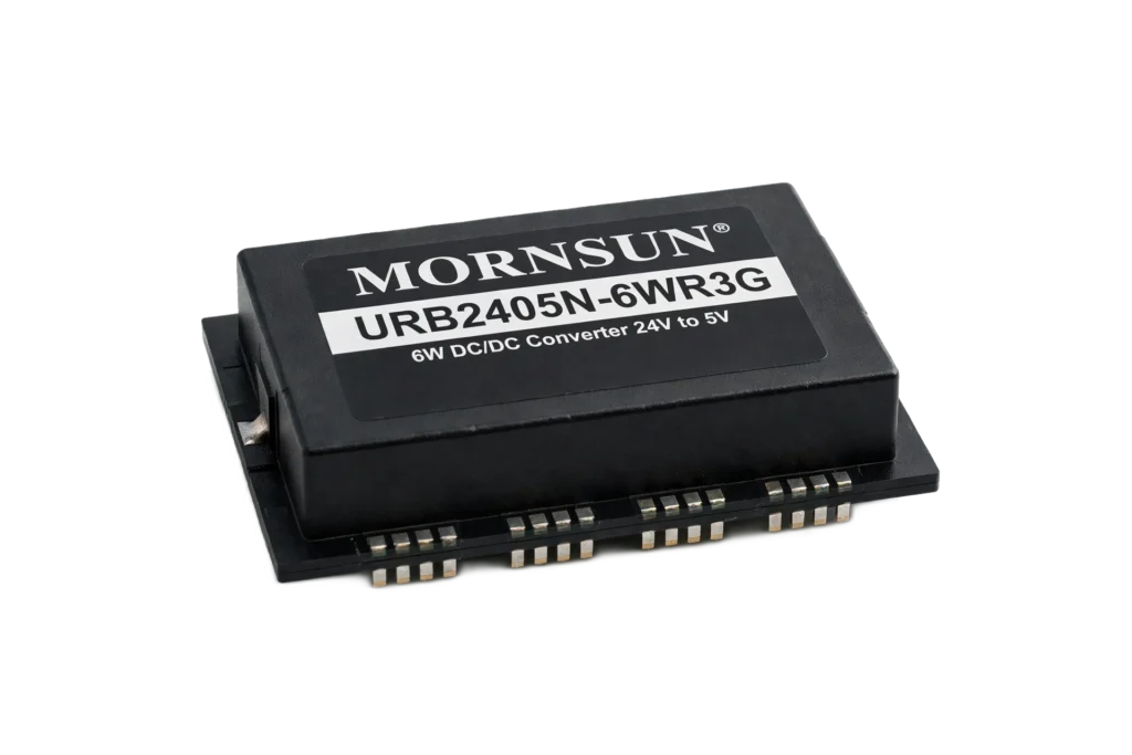
| Dòng sản phẩm | TD541SCANFD |
|---|
| Mã hàng | TD541SCANFD |
|---|
| Thương hiệu | MORNSUN |
|---|
| Dominant CANH output voltage | 2.75–3.5 4.5 |
|---|
| |V O(D) | | Figure 8, V = 0 V, R L = 60; TXD |
|---|
| Dominant CANL output voltage | 0.5–1.5 2.25 |
|---|
| V O(R) Recessive bus voltage | Figure 8, V = 2 V, R L = 60: Ω 2–2.5 3 V; TXD; Figure 8 V = 0V, t < t: ,; TXD: to(dom)TXD |
|---|
| V OD(D) Differential output voltage | 1.5–3 V; V =4.75 V to 5.25 V, RL = 50: to 65Ω; CC; Figure 8 V = 5 V, R L =: 60 Ω –0.12–0.012; TXD |
|---|
| V OD(R) Recessive differential output | voltage; V = 5 V,No load: –0.5–0.05; TXD |
|---|
| I IH TXD High-level input current | V = 2 V: 4 uA; TXD |
|---|
| I IL TXD Low-level input current | V = 0.8 V: -4 uA; TXD |
|---|
| R Internal TXD Pull up Resistor | 9.1 kΩ |
|---|
| V IT+ Positive-going input threshold | voltage: 750 900 mV; Figure 11 |
|---|
| V IT– Negative-going input threshold | voltage: 500–650 mV; V hys Hysteresis voltage (V - V ): 120mV |
|---|
| IT+ | IT –; I OH = –4 mA, Figure 9: V – 0.4 V–– 0.2; IO IO |
|---|
| V OH High-level output voltage | I OH = –20 uA, Figure 9: V – 0.1; IO; I OL = 4 mA, Figure 9: 0.2 0.4 |
|---|
| V OL Low-level output voltage | I OL = 20 uA, Figure 9: 0 0.1 |
|---|
| C I (CANH or CANL) | V = 5 V, V I = 0.4 sin (4E6πt): + 2.5 V–13 pF; TXD |
|---|
| C ID Differential input capacitance | V = 5 V, V I = 0.4 sin: (4E6πt)–5 pF; TXD |
|---|
| R ID Differential input resistance | V = 5 V: 19–30 52 kΩ; TXD |
|---|
| R IN Input resistance (CANH or | CANL) V = 5 V: 9–15 28 kΩ; TXD |
|---|
| R I(m) | V CANH = V CANL: –1%–0% 1%; [1 – R ) / R ] × 100% |
|---|
| IN(CANH IN(CANL) | CANH, CANL pin to GND: ±15 kV |
|---|
| HBM | Other pins: ±2 kV |
|---|
| EFT IEC61000-4-4:Perf. Criteria | B CANH, CANL and GND: ±2 kV |
|---|
| Surge IEC61000-4-5:Perf. Criteria | B CANH, CANL and GND(Common: Mode)–±2 kV |
|---|
| Isolation voltage | 5000 VDC |
|---|
| Insulation Insulation resistance | 1 GΩ |
|---|
| Isolation capacitor | 3 pF; V = V or 0 V, VCM = 1 kV,: transient |
|---|
| CMTI Common Mode Transient | Immunity TXD CC: 25 kV/us; magnitude = 800 V |
|---|
| t Propagation delay TXD On to bus | active: 80–150 ns |
|---|
| t Propagation delay TXD Off to bus | inactive RL = 60 Ω, CL = 100 pF, see: 80–200 ns |
|---|
| t Propagation delay RXD On to receiver | active Figure 10 and Figure 12: 60–300 ns |
|---|
| t Propagation delay RXD Off to receiver | inactive: 60–250 ns |
|---|
| t Dominant time-out time | CL=100 pF: 2–5 ms |
|---|
| Parameters | Value Unit |
|---|
| Trọng lượng | 0.9(Typ.) g |
|---|
| voltage | voltage |
|---|
| TD541SCANFD is a CAN of a style of separation | transceiver with the ability of differential: signal transmission between the bus and CAN protocol |
|---|
| controller, it the inner integration insulate DC/DC | power supply.which is compliant with ISO11898-2: standard. |
|---|
| Short-circuit protection: TD541SCANFD has | current-limiting protection to prevent the: drive circuit from short-circuiting to positive and negative |
|---|
| supply voltages. The power dissipation increases | when a short circuit occurs. The short-circuit: protection function protects the driver stage from damage. |
|---|
| Over-temperature protection: TD541SCANFD | has over-temperature protection. When the: junction temperature exceeds 160°C, the current in the |
|---|
| driver stage will decrease. Because the drive tube | is the primary energy consuming component,: current reduction can reduce power consumption and |
|---|
| reduce chip temperature. At the same time, the rest | of the chip remains functional. |
|---|
| TXD_OTD | Figure13. Typical application circuit; Figure14. Typical Application of PCB layout |
|---|
| In General, V and V can be shorted(Figure 14) if | the controller doesn't support 5V signal input,: it can power 3.3V for V |
|---|
| CC IO | IO. |
|---|
| When the module is in normal condition attach STB | Pin to GND2; Figure15. Port protection circuit for harsh: environments |
|---|
| Component | Recommended part, value Component: Recommended part, value |
|---|
| R3 | 1MΩ D1、D2: 1N4007 |
|---|
| C1 | 1nF, 2kV D3: SMBJ30CA |
|---|
| T1 | ACM2520-301-2P R: 120Ω; terminal |
|---|
| GDT | B3D090L R1、R2: 2.7Ω/2W |
|---|
| essential to add an adequate protection circuit to the | CAN signal ports to protect the system from: failure and maintain a reliable bus communication. |
|---|
| protection device. Parameter description lists a set | of recommended circuit parameters, which: can be adjusted according to the actual application |
|---|
| situation. Also, when using the shielded cable, the | reliable single-point grounding of the shield: must be achieved. |
|---|
| V CC Power supply | 4.75–5 5.25 V |
|---|
| V Power supply(Logic Side) | 2.75–5.25 V |
|---|
| V I or V IC Voltage at any bus terminal (differential | mode) –12–12 V |
|---|
| V IH High-level input voltage | TXD 2 V |
|---|
| V IL Low-level input voltage | TXD–0.8 V; Driver -70 |
|---|
| Receiver | V =5V -4; CC; Driver–70 |
|---|
| T A Operating temperature range | -40 to 125°C |
|---|
| I Recessive mode current | 20 35 mA |
|---|
| Signaling rate | 40–5000 kbps |
|---|